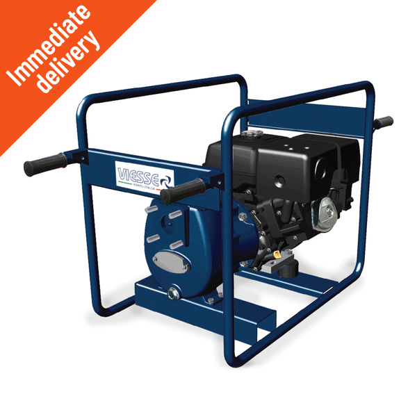
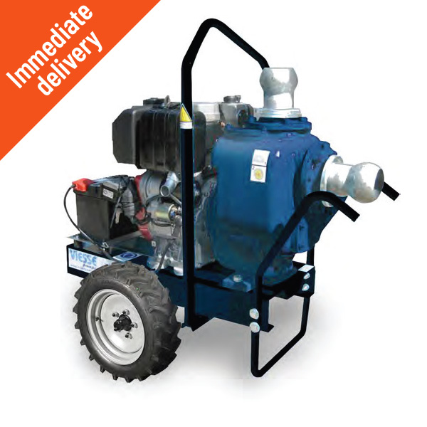
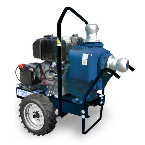
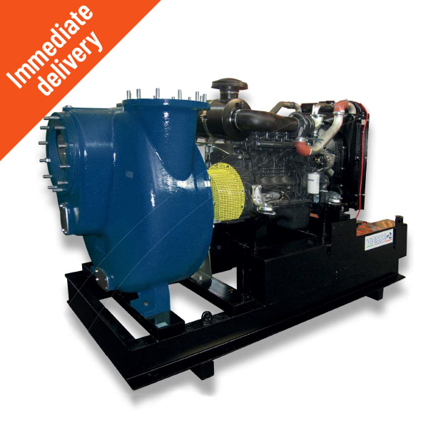
Self-priming centrifugal engine-driven pumps with an open impeller and free solids passage suitable for pumping slurry containing materials with various particle sizes and hardnesses.
They combine the huge benefits of the RHS system with the more stringent demands required for industrial applications – for mainline and processing operations – water treatment and many other applications.
RB self-priming engine-driven pumps: all the benefits of the RHS system when pumping liquids
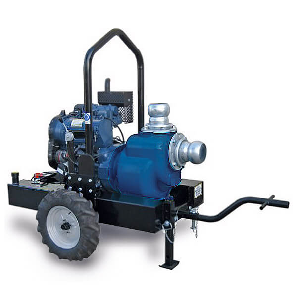
Self-priming pumps with open impeller
SELF-PRIMING PUMP RB625+TT
| RB625B GLD62 +TT | RB625B GYN388 +TT | RB625A GYN488 +TT | RB625A GYN498N +TT | |
|---|---|---|---|---|
| RPM | 1500 | 1800 | 1800 | 2000 |
| P MAX pump (kW) | 9.5 | 21 | 25 | 37 |
| Q MAX (m³/h) | 330 | 370 | 400 | 400 |
| H MAX (m) | 17 | 25 | 27 | 33 |
| Ø Inlet/outlet DN (mm – “) | 150 (6″) | 150 (6″) | 150 (6″) | 150 (6″) |
| Free solids passage MAX size (mm) | 73 x 50 | 73 x 50 | 73 x 50 | 73 x 50 |
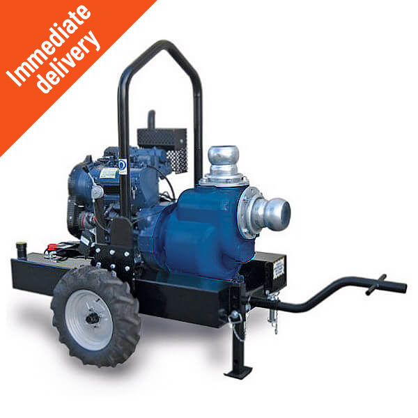
Self-priming pumps with open impeller
SELF-PRIMING PUMP RB831+TT
| RB831B GY49N +TT | RB831B GY498 +TT | RB831A GN4S0 +TT | RB831A GN6M2 +TT | |
|---|---|---|---|---|
| RPM | 1700 | 1800 | 1900 | 2000 |
| P MAX pump (kW) | 41 | 43 | 65 | 100 |
| Q MAX (m³/h) | 600 | 650 | 750 | 750 |
| H MAX (m) | 30 | 34 | 43 | 47 |
| Ø Inlet/outlet DN (mm – “) | 200 (8″) | 200 (8″) | 200 (8″) | 200 (8″) |
| Free solids passage MAX size (mm) | 78 x 75 | 78 x 75 | 78 x 75 | 78 x 75 |

Self-priming pumps with open impeller
SELF-PRIMING PUMP RB1031+TT
| RB1031A GY498 +TT | RB1031B GY49N +TT | RB1031B GN4S0 +TT | RB1031A GN4T2 +TT | |
|---|---|---|---|---|
| RPM | 1500 | 1600 | 1900 | 1900 |
| P MAX pump (kW) | 43 | 39 | 65 | 79 |
| Q MAX (m³/h) | 750 | 750 | 900 | 900 |
| H MAX (m) | 30 | 30 | 42 | 45 |
| Ø Inlet/outlet DN (mm – “) | 250 (10″) | 250 (10″) | 250 (10″) | 250 (10″) |
| Free solids passage MAX size (mm) | 85 x 85 | 85 x 85 | 85 x 85 | 85 x 85 |
SELF PRIMING
The separation type self-priming system operates inside the specially designed body. In greater detail, the liquid fills the pump body through an upper opening when the pump is stopped. Then, when the machine is started, the impeller transfers the liquid from the suction zone to the discharge zone. This occurs in a very short space of time (1-2 sec). At this point, an air-liquid circuit is set up between the impeller, volute and body. The liquid returns to the volute through the hole specially made on its edge.
The speed and vorticity of the mixture which forms draws the air into the suction zone, entraining it and releasing it into the discharge zone, where the speeds are lower and the air itself can separate due to the difference in densities. The faster the circuit time of the mixture, the shorter the priming time.
All this happens until the vacuum which is created in the intake duct reaches the same level as the head of the liquid from the pump. At this point, the liquid enters the impeller and the pump starts working like a normal centrifugal pump.
The priming process occurs automatically whenever air is present in the intake duct. The air expelled from the body flows towards the discharge line as an air bubble. It is therefore necessary for the discharge line to slope constantly upwards. The RHS system offers optimised priming as the volute, which is independent of the body, is designed and positioned for optimised efficiency.


